Friday, December 12, 2014

Need help: uxul.org data

The visual6502.org bulk data store has gone down:
http://uxul.org/~noname/visual6502/

Do you have any data from this before it went down?  If so, please contact me: JohnDMcMaster at gmail dot com

Wednesday, December 10, 2014

They're multiplying!

I've been continuing to troubleshoot the Super IIIA SEM and, by using putty, have discovered that the leak is in the column.  I'm having some trouble figuring out how to safely disassemble it to fix the leak.  More on that later.

In the meantime, I've been exploring alternate paths.  My ISI Super IIIA had a baby SEM!

I found someone selling an ISI M-7, a small tabletop SEM from the mid 70's.  The catch?  I had to drive from the SF Bay Area down to LA to pick it up (385 miles each way).  He is a semi-retired Cambridge SEM technician, not sure how the ISI unit got into the mix.  The landscape:


Its the blue unit on the right.

I was already aware that the PMT assembly had sustained some damage but was unsure how substantial.  Unfortunately the PMT tube itself was cracked:


Fortunately I found one reasonably cheap on eBay that's in the mail.  IIRC the Super IIIA uses the same PMT so I could borrow it from that if necessary.  Additionally, an IC came lose in the PMT base that doesn't really match with the socket.  Need to do some work to figure out what happened.

After sitting in the garage for some years it was a bit of a mess.  For example, here's a close up of the vacuum manifold:


After some cleaning it looked a lot better but still has a lot of rust:


Next, I wired everything up to the best I could given that not all the cables were still labeled:


I love the enormous military grade connectors.  It didn't come with an AC cord (requiring a military grade connector) but I was able to borrow one from the S3A.  A few other things are required in addition to the core equipment shown above:
  • Roughing pump
  • Diffusion pump circulation pump / cooling
  • Variac to step down 120VAC to 100VAC input voltage

Turned the power on and no smoke came out.  The "replace anode" light came on which I'm not sure what to make of yet.

Unfortunately I don't have a 5/8" adapter for my vacuum pump so I can't attempt to rough it down.  Ordered a $10 KF16 adpater from Tedpella, waiting for it in the mail along with the PMT replacement.

Sunday, October 5, 2014

Updated AmScope MU800 driver

Can be found here: http://lkml.iu.edu/hypermail/linux/kernel/1410.0/02700.html

Hopefully will get merged into the kernel soon.  Over previous candidate this fixes some minor formatting issues and removes a serial number comparison check (read: only would have worked with my camera).

I also have traces from an MU300 and might merge those in soon.  Shout out if you'd really love to see MU300 supported on Linux.

siliconpr0n.org gets a facelift!

Thanks to Enrique Murias Fernández!, the original "2 minutes in vi" homepage has finally been replaced with something more proper:

http://siliconpr0n.org/

Getting a real SSL cert is on my radar.  I tried to get one from StartSSL but they never responded to me  Unfortunately, it may cost more than the web hosting...

Wednesday, October 1, 2014

Confocal microscope bringup

One of the biggest issue with the process of digitizing ICs is that, at least with the tools/people available to me, polygon capture is mostly done by hand.  If you look at most of the automated polygon capture systems they either rely on SEMs (sharp images) or confocal imaging (planar view reduces background noise).  SEM imaging has its place and eventually I'll having a working SEM (sniff...that's for another post)

Most confocal microscopes out there are intended for biological imaging.  You can, for example, tag cells with fluorescent dies and build up a 3D image.  In some cases you can even image live cells and get some pretty sweet 3D videos.

Of metallurgical / epi illuminated by far the most popular model out there is the Technical Instruments K2 IND.  I tried to get some from local industrial auctions but kept getting outbid.  After some online searching/negotiating I was able to get one at a reasonable price off of eBay:


The system didn't come with any objectives and is not computer controlled but is otherwise complete (also includes power supply, not pictured).  I saw other scopes using Nikon BD Plan objections but I'm unclear if this is wasteful over the Nikon M objectives: I don't see a way to use darkfiled functionality.  Anyway, I picked up a Nikon BD Plan 20x objective and the system did in fact work.

As an impulse buy, I had previously purchased a heavy duty Technical Instruments XY stage at industrial auction:


 The linear stage is actuated by Compumotor M-57 stepper motors and is equipped with quadrature equivalent output RSF Elektronik glass linear encoders (10 um resolution):


The encoders are nice but I can generally get away with running stepper motors in open loop so not sure if I will use them.  That said, linear encoders can be used to eliminate backlash which would be nice.

It also came with matched Compumotor M-57 motor controllers:


They run open loop and therefore do not take into account either encoder. A complete system with heavy duty stages, cables, drivers, etc and I think I only paid something like $120 net for it.  Also came with random nosepiece which got thrown in my junk drawer.

Finally, not shown is the Z column.  Its not motorized but its pretty heavy duty.  Its unclear to me if this setup was intended to be used with the K2 IND, but it looks heavy duty enough to support one.  It seemed a good match for this microscope and I began the conversion process by (gasp) cutting the Nikon microscope body in half so I could re-mount it to my Technical Instruments stand.  Target:


 But how to clamp this?  I have a smallish table top mill (Sherline 2000) with vices nowhere near the size of the stand.  But it just needs to be stable without super precision which opens things up a bit.  What if I could just hold it down with some plumbers tape?

So I took a small unused optical table and wrote a CNC drill program to drill some countersunk holes so that I could mount it to the table:


I can't remember how I drilled the first few holes to bootstrap it...

Anyway, this allowed me to securely fasten the remaining microscope body and clean up the sawzall cuts:


Got busy at work, broke my CNC mill with some unrelated work (its fixed now) and time passed.  I was looking into getting objectives and saw another K2 IND at industrial auction.  It turned out that it was likely going to cost me less to get another K2 IND with objectives at industrial auction than to buy objectives off of eBay.  And I ended up winning this system:


They're multiplying!

But this new system, a Zygo KMS 310 RT, is actually quite nice.  Intended for mask inspection, seems to have been some partnership between Zygo and Technical Instruments.  Anyway, it came with a lot of stuff:
  • Infinity corrected K2 IND (KMS310)
  • 4 Nikon CF Plan objectives (very nice)
  • XY DC servo motors with glass linear encoders
  • Linear and quadrature encoded DC servo Z motor (cause the thing weights so much its not manually actuated)
  • Piezo Z stage for fine focusing
  • Vibration isolated table w/ CRT.  This may be why it went for a bit low price: people maybe didn't want to deal with getting rid of this
  • No control system (probably drove down price)
  • Came with cables, some of which were cut
While I couldn't find much information on the KMS 310 RT, I did find some pictures of Zygo KMS450i which looks to have identical linear stages.  Its a monstrosity of a control box and probably just as well that I replace it with just what I need

But what do I need?  A bit of a problem: all of the XY stages I've ever worked on have been open loop stepper systems.  I'm now confronted with DC servos, a whole different paradigm.

My old boss liked to say that cheating is a valid engineering strategy.  Can we cheat?  yes we can!  Here are the two Technical Instruments bases I have:


They are made by the same company and the footprints look awfully similar.  Wonder if I can take the stepper stage and transplant it onto the KMS 310 RT?  Yep!


Now just the Z axis to deal with.  For starters I just attached a benchtop power supply and was able to get it to move around (its a DC motor after all).  But not very convenient.  If I was really determined I may have been able to remount a stepper in its place.  But its a good excuse to learn more about servo systems.

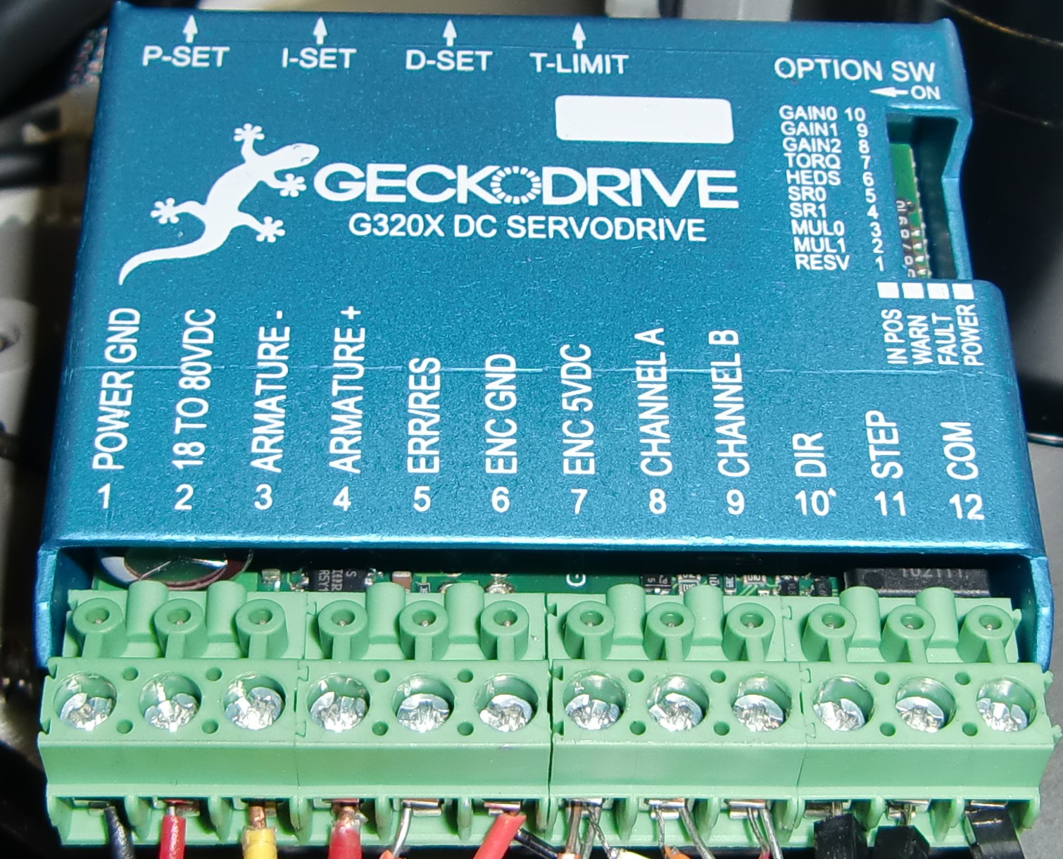
After doing some research and talking to people, Geckodrive Motor Controls seems to be pretty good quality and reasonable cost.  While most of their business is in stepper drivers, it turns out that they make a DC servo drive, the G320X Digital Servo Drive:


I ordered two of them, intending one to be used for X and one for Y.  But with the XY problem solved for the time being it seemed fitting to use it on the Z axis.

Next challenge: figure out motor pinout.  After some multimeter action I was able to trace the wires on the motor to the umbilical cord coming off of the KMS 310 RT (which I cut in half since I didn't want to buy $ circular connectors).  The encoder pinout was printed on the encoder but I had some problems getting it to work.  After some looking around, I found the website for the motor and learned the encoder was open collector.  After adding some 1k pullup resistors the encoder signals looked good on my scope and the Gecko accepted them.  Final test setup:


Last piece of the control system: need to generate step/direction pulses to the compumotor XY drivers as well as the gecko Z driver.  I already have a low cost indexer (pr0ndexer) I use on my Olympus BH2, so I simply made another one of those:


Fired up my cnc microscope program...and it worked!  All the gains are set for my BH2 system but those should be reasonably easy to adjust.

Proof of concept system overview:

 
But I'm not in clear water yet.  The original Nikon K2 IND seems to work fine in all accounts.  The KMS 310 RT works in normal epi mode, but doesn't let enough light through to be usable in confocal mode.  I could swear it worked before, not sure.  The problem should be solvable one way or the other with the worst case being that I replace it with the Nikon K2 IND.

Other future plans: I'd still like to get the original DC servo linear stages working.  They use sine-cosine encoders which are a bit more complex to use.   I also need to incorporate a levelling element (probably a mirror mount) so that chip remains in focus across the scan.  Once that's in place I can do my first scan.

Until next time!

Friday, June 13, 2014

CNC'ing SEM parts and 80386 and 80486 photography funding

I thought I'd give the whole crowdfunding thing a try: https://www.indiegogo.com/projects/the-intel-80386-and-80486/x/7938325

If you like the stuff you've seen here on my blog and on siliconpr0n.org, consider helping me recoup some of the costs and keep generating data

In other news...

Over the weekend I spent some time learning CNC stuff better and managed to get my Sherline 2000 CNC mill cranking out SEM parts.  Here's a backplot:


Everything is done in one pass with a 1/8" endmill to leave the part slightly attached on the two sides.  Here is a stock piece:


Milling started:


After a more:


Gasket fit check:


 Comparison with the original:


The original is stainless but thats a bit hard to cut on my system so I did aluminum.  Next I will cut a hole in it and attach a KW25 vacuum port.  This will allow me to attach a vacuum gauge to better understand if the SEM has a healthy vacuum system.

Sunday, June 1, 2014

Rolling with the SEM

Minor updates...

The SEM is off the pallet.  Used a cherry picker with some help from a friend to lift it one side at a time:


Now its on wheels and isn't quite so tall:


The rack on the left will hold the pump and maybe computerized control system.

I also got replacement vacuum hosing:


Its reinforced but still would collapse under vacuum.  Fortunately, I only need it a short length so I can connect stainless vacuum hose

Currently working on learning CNC better so I can make some new vacuum ports for a vacuum gauge.

I also got an EDS detector in the mail:


It needs some TLC but should still be fun, more on that later.

Also picked up some wire bonders at industrial auction:


The base unit seems to work but needs a microscope (check but need to make adapter) and acquire a tip ($30 on eBay) + spool/tensioner.  I don't have the latter which shouldn't be too hard to make but may require a lot of tweaking to get it working properly.

Finally, the microscope camera now has frame lock and has been upgraded to linux-next.  I tried to submit to linux kenrel but don't think it e-mailed out.  In case I get hit by a bus, here is my Linux AmScope MU800 camera driver: http://siliconpr0n.org/uv/mu800/0001-media-gspca_touptek-Add-support-for-ToupTek-UCMOS-se.patch  I also white-balanced my camera.  Unfortunately, the driver as written cannot reach the right thresholds.  Instead, I hard coded the RGB values in my local build.  Hopefully will fix these in near future...

Sunday, May 18, 2014

Cleaning the Super IIIA

Just like the toys I had when I was younger, some assembly was required.  Fortunately, everything was pretty obvious where it went and I got it all together.

However, there were two major components not supplied:
  • A method to convert from US power to 100 VAC (Japanese power evidently)
  • Diffusion pump cooling system
  • A roughing pump
 The first was solved by using a Variac to step down wall voltage slightly.  Evidently other Super IIIA users got a giant transformer with theirs.

I rigged up a pump I had laying around to cool the diffusion pump and it seems good to go.  Eventually I might add a peltier cooler but for now I'll just use a big water tank that should stay cool enough.

I have a roughing pump but the plastic oil watchglass was in pretty poor condition, causing the pump to leak oil.  Not only was the gasket torn, but the watchglass was cracked.  I ordered new gaskets and machined a new watchglass:


Although, all the dimensions looked pretty good and it fit snugly, it still leaked!  At this point I just epoxied the watchglass in place and called it a day.   No more leaks!

The Super IIIA has a 1" vacuum hose port and I happened to have a 1" vacuum hose adaptor for my pump.  Unfortunately, I didn't have any 1" vacuum hose to join the two.  There was a small bit of hose that had been cut off from the original pump that was just enough to join the two together:


(not vacuum hose on the left but gives you the idea).  However, its short enough that its fragile and so I ordered some reinforced 1" hose to replace it.

Time to plug it in and see what happens.  Here is the startup panel:


First, I pressed the power button and I think a pilot light came on.  No other signs of life yet.  I then pressed the RP button and some fans whirred on (probably for pressure measurement).  As my roughing pump takes 120V I did not wire it to the 100V RP output and so manually switched it on.

I let the pump run for a bit to evacuate the piping leading up to the chamber.  Although I didn't have a pressure gauge on, the pump eventually got very quiet with no burping to indicate any substantial vacuum leaks.  Then, I pressed the button to evacuate the chamber.  Pump got noisy again as it started to bring down the chamber.  But stayed noisy: it leaked bad :(

Next disassembled easily accessible areas so that I could clean it and grease gaskets.  One interesting bit that it exposed:


Part of the beam steering optics right below the Wehnelt.  The Wehnelt assembly is also interesting (and filthy!):


Everything around the filament is quite dirty.  Lapointe recommended Wenol which seems to have worked well enough.  After cleaning with Wenol, components were sonicated in water and then rinsed with IPA.  I don't think I'm at high enough vacuum where water outgasing will be a problem but I can bake them later worst case.

I imagine these old SEMs are generally not well maintained and without greasing the gaskets, they dry out and develop bad vacuum leaks.  This leads to short filament life and subsequently the filament sputtering all other.  And burned out for that matter:


Hmm...what to do?  Fortunately, there are a number of vendors that sell replacement filaments.  I did some research and settled on ME Taylor, the same people that Lapointe bought his filaments from:


They seem fairly simple and I'm hoping I can rebuild them in the future instead of ordering more.  Depending on how easily I fix the vacuum leaks, the 10 could last me some time or burn through real quick.  So far this is by far the largest purchase I've had to make since I already had the Variac and roughing pump.

After cleaning and greasing, it doesn't leak badly but I still hear some burping,  I'm unclear if this is a safe level to use the DP or, more likely, that the DP won't be able to sufficiently lower the vacuum.  Next on the agenda is to machine a standard vacuum adapter (probably NW25) for one of the unused chamber ports.  This will allow me to attach vacuum gauges to give me a better idea if it actually is leaking badly / in a spot I care.  There is a Pirani gauge built into the SEM but its not very accessible.

It came with the schematics which I was able to scan.  Also, thanks to lapointe2 I also have the user manual.  Both are in fairly crude, disorganized forms as of this writing, but they can be found here along with other info I collect.

Saturday, April 19, 2014

A new toy arrives: introducing the Super IIIA

What weighs 865 lbs, is probably older than me, and has a radiation trefoil on it?  Its our friend the ISI Super IIIA, at last sitting in my garage:


This post is about my initial impressions unpacking it.  In general, it is slightly larger than the noisebridge system (ISI TV Mini-SEM) and has several enhancements.

Here is the console:


The left side mostly concerns with zoom and display.  The right side has some focus controls and pump control.  There are several empty bays on the far left presumably intended for expansion modules / customization.  It came with a cover plate that sort of fits there but with no real way to secure it down.  The upper left CRT is for normal viewing while the right is intended for photography.

It also has a cute little warning sign on top:


Physics is not my strong point but I think it goes something like this: the electron beam strikes the sample and excites the atoms it hits, ionizing some of them . Eventually they drop in energy and emit an x-ray, similar to how lasers work.  However, there is a fair amount of shielding and the column is probably only 10kV.

Moving on to the vacuum system, here is the inlet for the roughing pump:


Above I'm checking connection with a 1" tube.  I plan on connecting a KF25 half nipple so that I can adapt it to my Varian DS-42 rotary vane pump.

This port connects to a vacuum distribution network that includes a diffusion pump:


Presumably the pump has oil but haven't checked.

The diffusion pump external cooling lines had been pinched under the SEM during shipping.  I was able to use a car hydraulic lift to prop up one side of the SEM and un-pinch it.  I will need to add a circulating pump to cool it.  There is also an external filtering assembly that I may or may not use.  The noisebridge system by contrast had a smaller air cooled diffusion pump.

The roughing pump, diffusion pump, and chamber are tied together via an electronically controlled valve:


The buttons should allow the chamber to switching between roughing pump, diffusion pump, and vent.  The noisebridge system was manually controlled.

But what is the vacuum system without the electron beamline?  The beam originates here:


I haven't checked to see if the filament is intact.

And enters various electromagnetic optics that allow it to be properly magnified and focused here:


Both these pieces have unusually high wear.  lapointe2 had a note about filaments burning out.  Talked to a few people and the running theory is that it has a vacuum leak that is causing excessive filament wear, maybe same issue in both.  Hopefully I can grease up the system, monitor vacuum levels, and avoid such problems.

Eventually it snakes its way into the chamber.


Hard to see in above picture, but there are three instrument ports with only one used.  Presumably this allows adding EDS or other accessories.  I plan to use one or two to install better pressure monitoring.  Close up of the interesting bits:


On top the beam exits from the beam steering optics to the stage below (not shown, more on it later).  To the left we can see the detector:


The grid is used to bias the sensor to help with sensitivity or something...read up on this before and need to refresh my memory.  Anyway, the white bit behind it should be the scintillator that emits a small bit of light when the sample emits an electron that strikes it.  This is then passed to the photomultiplier tube:


The signal then feeds into the various electrical boxes that convert it into vertical, horizontal, and intensity signals to feed the CRTs:


Going back to the chamber, here is the sample stage as seen from the outside:


It has mechanical digital read out which is kind of cool.  Unfortunately, its also pretty coarse so I'm concerned it won't be easy to position things at high magnification.

And the inside:


It has numerous electrical feedthroughs.  I haven't come up with a use for them yet but it does leave a lot of possibilities open.

Finally, I ordered some sample mounting supplies from Ted Pella (Ted Pella #16216: Aluminum Specimen Mount, OD32 x 10 mm):


The specimen mount on the stage image previously shown has a smaller one placed on top of it that came with the SEM.  It did not fit and so was packaged with aluminum foil:


As well as conductive tape to hold specimens in place (Ted Pella #16084-6: PELCO Tabs, 6 mm OD):


The specimen holders are quite large...should be able to hold several specimens per holder.

Next steps forward are to:
  • Get it off the pallet so it can be moved around
  • Power on the console
  • Setup diffusion pump cooling
  • Attempt to pump down the chamber
  • Image something!
One oddity is that it requires single phase 100VAC.  I should be able to supply this with a variac without problem.

Longer term goals:
  • Turbo pump?  Depends how well the diffusion pumping works
  • Computer imaging
  • Computerized stage control
But those only matter if I can get it working at all.  Fortunately, someone else rebuilt an identical unit which should also help.